Fatigue analysis
Fatigue failure
Fatigue failure is the primary cause of structural failure. Because of this, fatigue analysis is today often a well-integrated part of the product development cycle. Starting with version R12, the LS-DYNA package includes both a frequency-domain fatigue solver and a time-domain fatigue solver. The latter offers the possibility to perform fatigue analysis for highly non-linear events. The time-domain fatigue solver is fully coupled through element stress/strain-computations making it compatible with most of the solvers included in LS-DYNA today.

The time-domain fatigue solver offers several useful features, for example:
- Stress- and strain-based fatigue
- Multiaxial fatigue options
- Mean stress correction options
- Restart analysis option
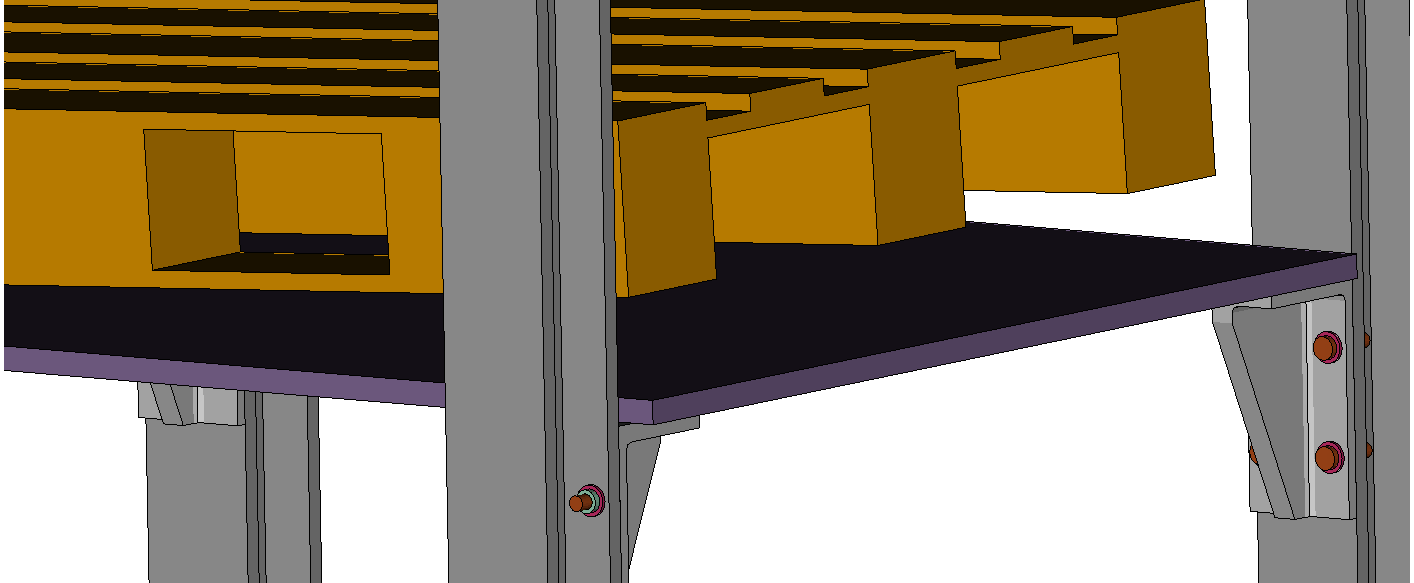
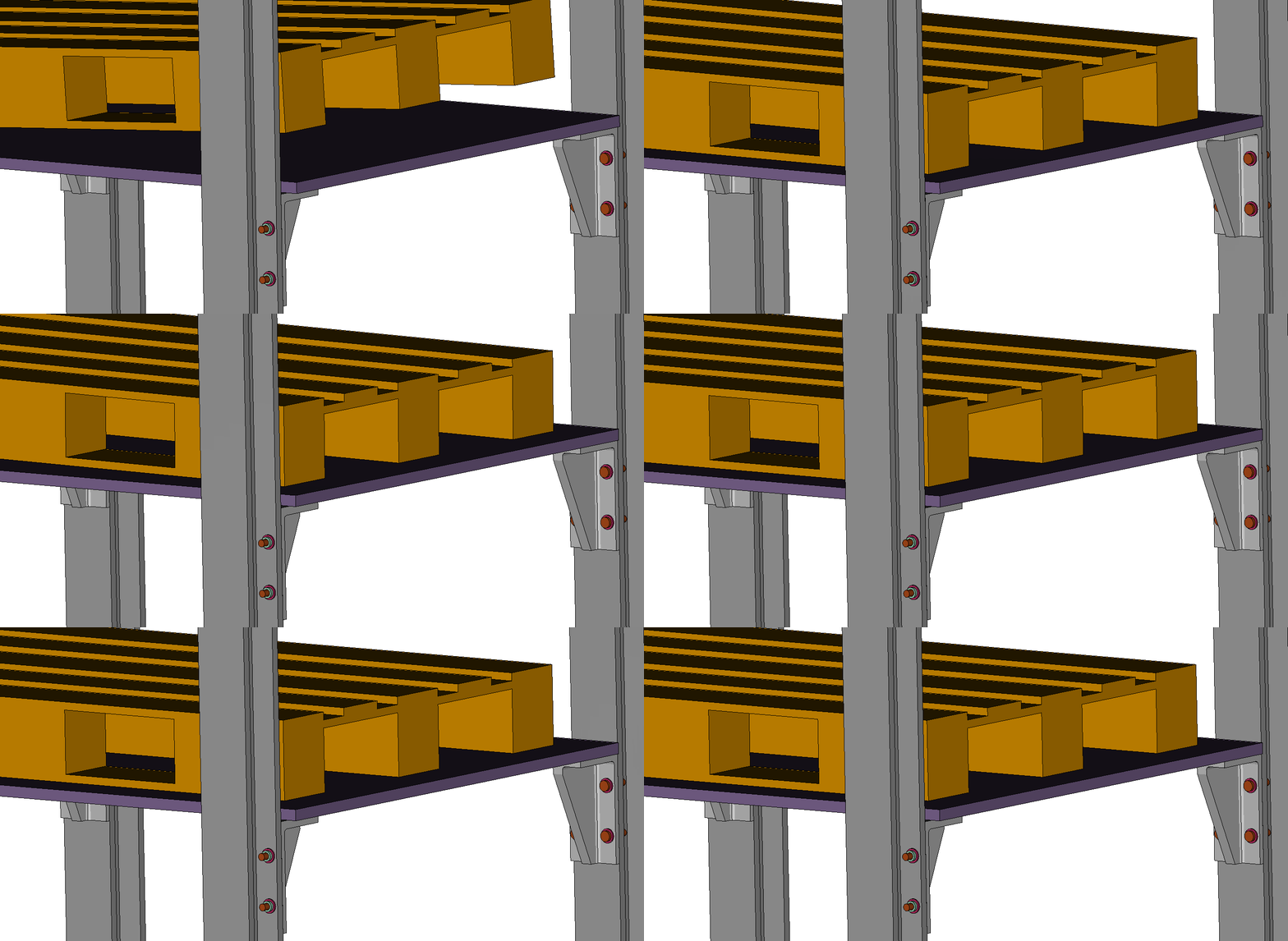
This case study shows a fatigue analysis using LS-DYNA, evaluating the radii in a bracket for the case of a pallet drop. The load case corresponds to a heavily loaded pallet being roughly set down on a shelve, i.e., dropped from the height of 10 mm with an impact angle of 3 degrees. This load case will contribute to the accumulated fatigue damage of the shelve brackets and must therefore be analyzed. Since this is a very dynamic event, the bracket's stress history cannot be determined accurately using a static analysis. Instead, a realistic dynamic simulation is made in LS-DYNA, which provides an accurate stress-time history as the basis for the fatigue calculation. To estimate the fatigue damage of the bracket radii, a highly resolved mesh must be used at these locations. To avoid large and time-consuming FE-models, sub-modeling is applied. The solution strategy can be summarised as follows:
- Explicit time-dependent simulation of the impact
- Coarser mesh
- Interface output for sub-modeling
- Time dependent sub-model analysis
- Fine mesh.
- Using the interface output in (1)
- Element output (elout) of elements for fatigue analysis
- Time domain fatigue analysis
- Only on selected highly stressed elements
- Stress based, high-cycle fatigue
- S-N curve input
Step 1: Impact simulation
This LS-DYNA model contains the entire structure and uses a medium resolution mesh. The mesh is fine enough to yield accurate displacements/velocities at the selected interface areas of the sub-model. The bolts connecting the brackets to the frame are modeled with solid elements and are pre-tensioned. For calculating fatigue damage, applying the correct preloading from gravity and tensioned bolts is crucial since it greatly affects the mean stress level and effective stress amplitude, and therefore the calculated fatigue damage. Appropriate sub-model interfaces are selected for output through the *INTERFACE_COMPONENT_{OPTION}-keyword.
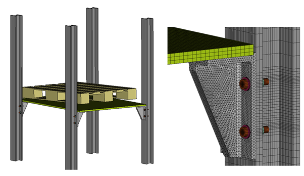
The simulation time is selected to be long enough to cover all stress peaks that may contribute to the fatigue damage.
Step 2: Sub-model of the bracket
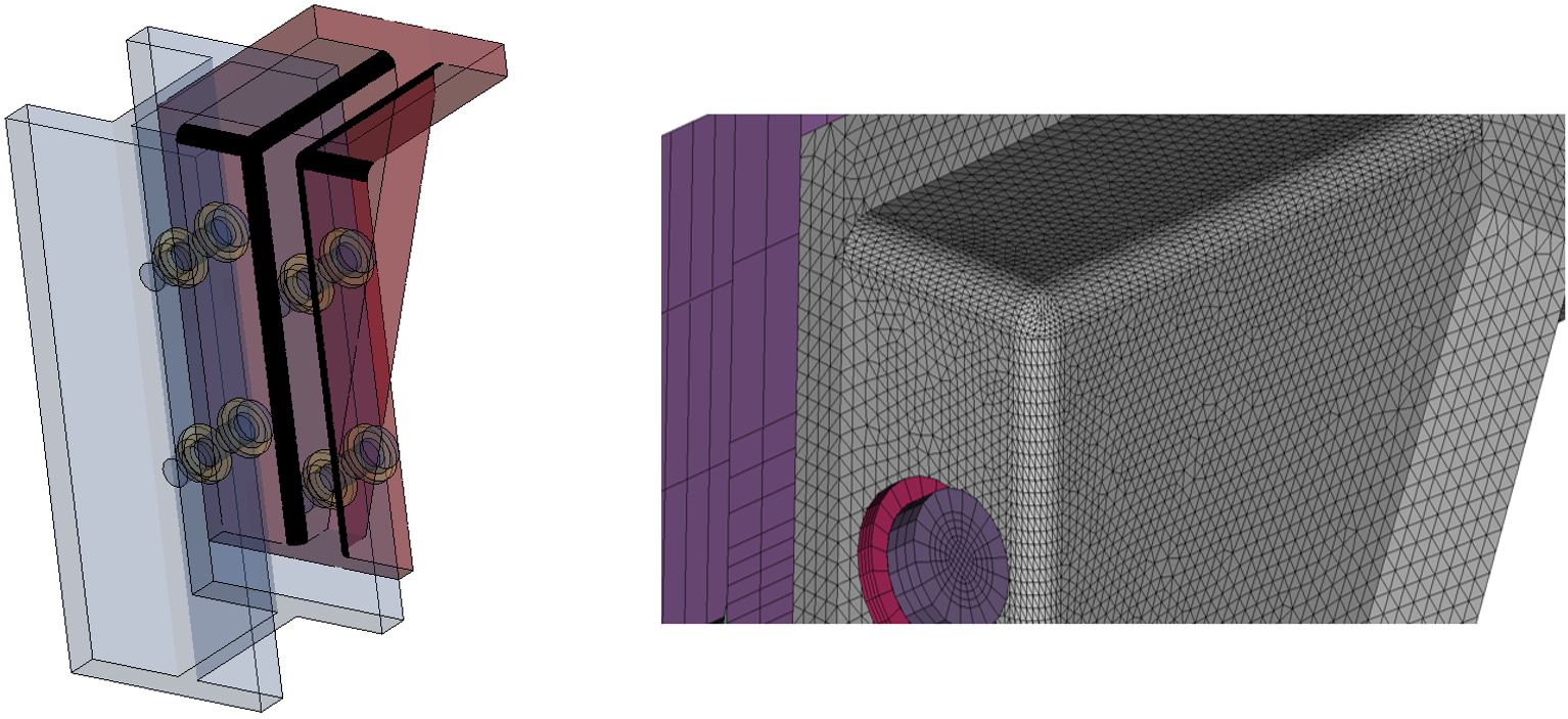
Analysing only a portion of the large model makes the evaluation less time-consuming. The bracket mesh is refined for better resolution of the stress gradients, especially at the radii. The sub-model is driven at selected interfaces by *INTERFACE_LINKING_{OPTION}-keyword using interface data from the impact simulation. To further reduce the input to the time-domain fatigue solver, the keyword *FATIGUE_ELOUT will be used. Using this keyword, fatigue analysis will only be performed on the most stressed elements that have been selected and output through *DATABASE_ELOUT. In this case, only the radii are of interest, so only the elements in the radii are output to the ELOUT database.
Step 3: Fatigue analysis and results
The element stress history is in a case like this very dynamic. A rainflow-counting algorithm is automatically applied to the recorded element stress histories in the fatigue solver to perform the fatigue cycle counting. After the cycle counting is finished, Palmgren-Miner's rule is used to calculate the cumulative fatigue damage ratio.
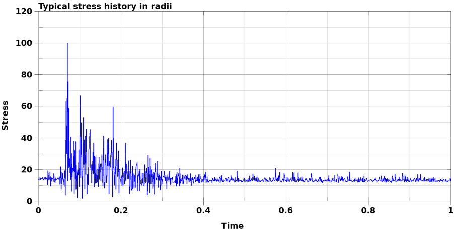
The fatigue material data is defined through *MAT_ADD_FATIGUE. The analysis is set-up as a stress-based (high cycle) fatigue analysis, based on principal stress and using a pre-defined S-N curve. *FATIGUE_MEAN_STRESS_CORRECTION and *FATIGUE_MULITAXIAL are included to consider the preloading effects appropriately and account for a multiaxial stress state at the radii.
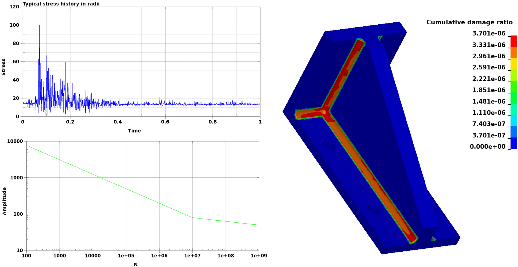
In this case, the bracket will be able to sustain 2.7*106 impact events before the radii fails.
In conclusion
The Time-domain Fatigue Solver in LS-DYNA R12.0 enables the engineer to perform fatigue analysis of structural parts without simplifying the model or the load case. This means that fatigue analysis can now yield results that better represent the real loading of the shelves during operation.
To learn more
Simulations have time and again proven to be a cost-effective product development tool that avoids costly tooling redesign. We have the software and knowledge required so that you may learn to perform these simulations yourself. We will guide you all the way, including training and support. To learn more, please contact one of our technical experts listed on this page.