Sloshing analysis of a fuel tank
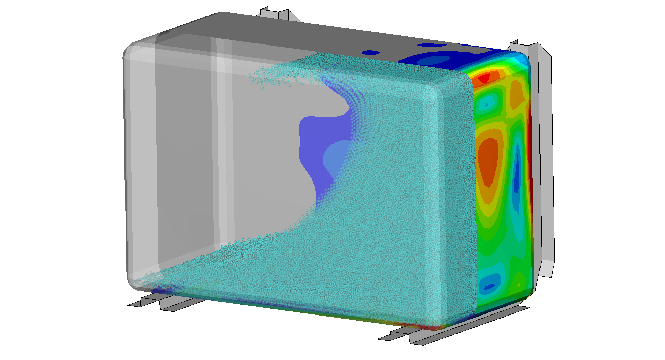
Complex boundary conditions made intuitive
When dealing with complex systems it can be a challenge to create appropriate boundary conditions and loads. We demonstrate this here by looking at the calculation of stresses and deformations of a fuel tank containing sloshing fuel. Creating boundary conditions and pressure loads on the tank that accurately represents the sloshing fuel can easily become a project within itself. To further add to the complexity, a product often undergoes several different evaluations within the organization that all need specific boundary conditions and loads, making the array of simulation models required large and complex.
A more straightforward way to capture complex boundary conditions, such as fluid sloshing, is to use the wide range of multiphysics capabilities within LS-DYNA.
In the case presented here, you can learn how adding and solving more advanced physics can make the work more intuitive, reduce complexity, and save time within the organization.
Product development enhancements
It is highly beneficial for product development to use simulations to minimize the need for expensive prototypes. In the simulation, it is easy to change things such as wall thickness, dimensions, and add reinforcements. Traditionally, engineers need boundary conditions for the loading and evaluation of the component. In the fuel tank case, this could, for instance, be a maximum pressure obtained from testing a similar product. These loads gathered from testing might be reasonable to use when the design changes are small, but for a more substantial design change such as adding a baffle in the middle of the tank, the completely change in fluid and structure dynamics would make the loading based on the test data invalid.
A more intuitive way to solve the problem is to model the fluid-structure interaction and use a global parameter such as the acceleration of the whole vehicle, which is not much affected by changes in the tank design. The vehicle acceleration is therefore a much more suitable boundary condition. The inquiry of vehicle accelerations is also more intuitive, as these can be sampled from existing products by testing or numerical simulation. There is also a higher chance that this data already exists within the organization.
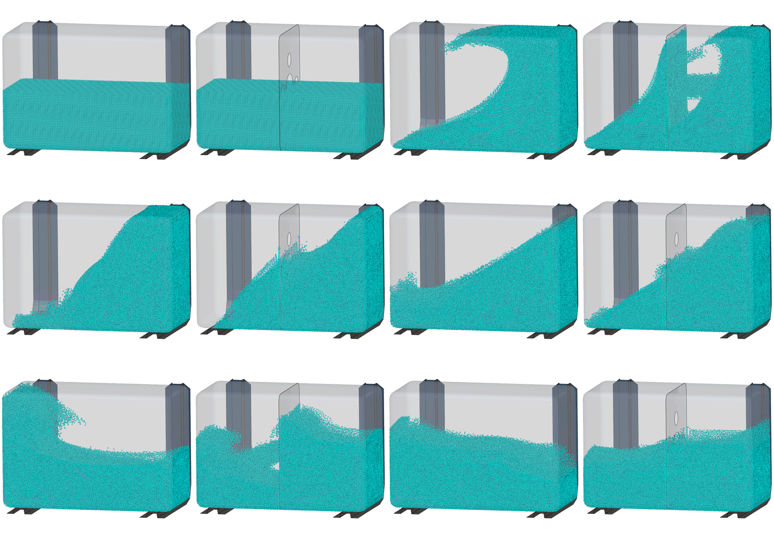
The following simulations were performed in LS-DYNA using a standard non-linear finite element model of the tank, coupled with a smoothed particle hydrodynamics (SPH) description of the fuel. The fuel is discretized as SPH particles that are in full contact with the tank in a coupled fluid-structure interaction (FSI) model. The whole system is loaded using gravity and acceleration due to a sudden braking of the vehicle. One can see that the baffle clearly influences the dynamics of the fluid to a great extent and therefore also the pressure loading on the tank.
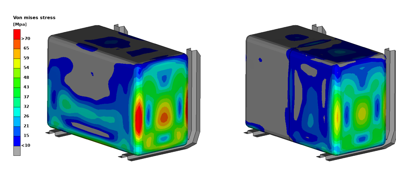
Looking at the stresses in the tank, one can see how much the change in dynamics affects the tank's structural integrity. The two design iterations were performed by only changing the tank's design, without having to come up with new boundary conditions. This facilitates rapid tests of new design ideas and continuous product improvements.
System development
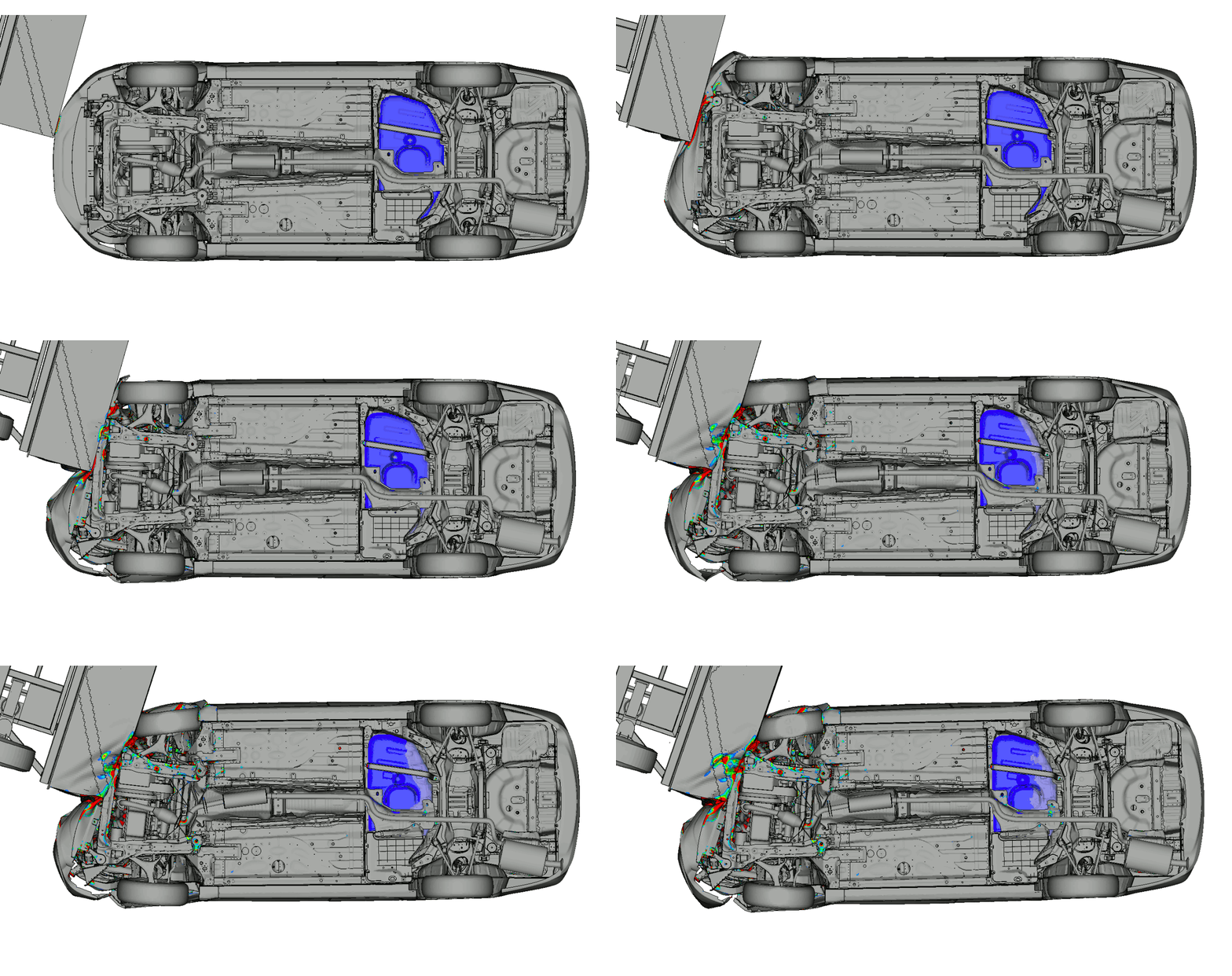
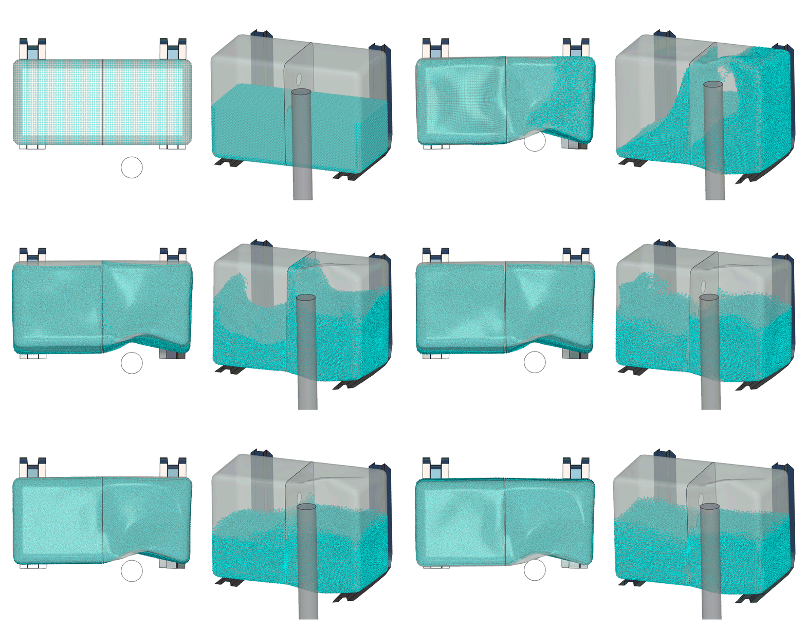
Another great benefit to this method is that other departments can use the same model for system evaluations. The fuel tank could be included in a crash simulation to better understand its performance during such loads. It would also contribute to the overall system validity, as it provides a more accurate dynamic response. Below you can see a simulation where a pole hits the tank, testing the tank's integrity and the brackets that support it.
To learn more
Simulations have time and again proven to be a cost-effective product development tool that avoids costly tooling redesign. We have the software and knowledge required so that you may learn to perform these simulations yourself. We will guide you all the way, including training and support. To learn more, please contact one of our technical experts listed on this page.
The car used in this demonstration is a modified version of the publicly available Honda Accord model, provided by NHTSA, https://www.nhtsa.gov/crash-simulation-vehicle-models.