Short Fiber Reinforced Plastics
Strength evaluation before manufacturing - is that possible?
Short fiber reinforced thermoplastics have been used since the middle of the last century, but calculating these parts' structural strength has been a challenge. It turns out that to get accurate predictions of the material strengths, one needs to account for the fiber orientations. The orientations will, in turn, depend on the injection molding process. To solve this problem, DYNAmore offers a complete simulation software solution to verify the strength of the final component before manufacturing any tooling.
Why numerical simulations?
Our primary software tool LS-DYNA has always been committed to representing the actual physics of structural problems to an increasingly higher level of detail. Even though advances in numerical solution techniques makes it technically possible to do this, why should one bother? Well, the reasons for performing simulations for your products are several. Some of the most common reasons we encounter in our daily work with customers are
- understanding poor (or good) product performance
- establishing which parameters that are important to control in your process, i.e., that influence the product performance
- a virtual copy (or a digital twin if you like) of your process and product, facilitates studies of changes and improvements to the product, without potentially costly experimental studies, including manufacturing of new tools or molds
- optimization of product performance is made possible
Our technical solution – Case study: polymer bumper front
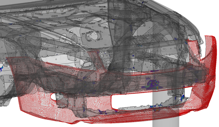
Here we demonstrate our solution for a bumper front. There are several strength requirements on the bumper front, but we will look at an impact test. The bumper front is a large fiber-reinforced component, which requires big and expensive tooling.
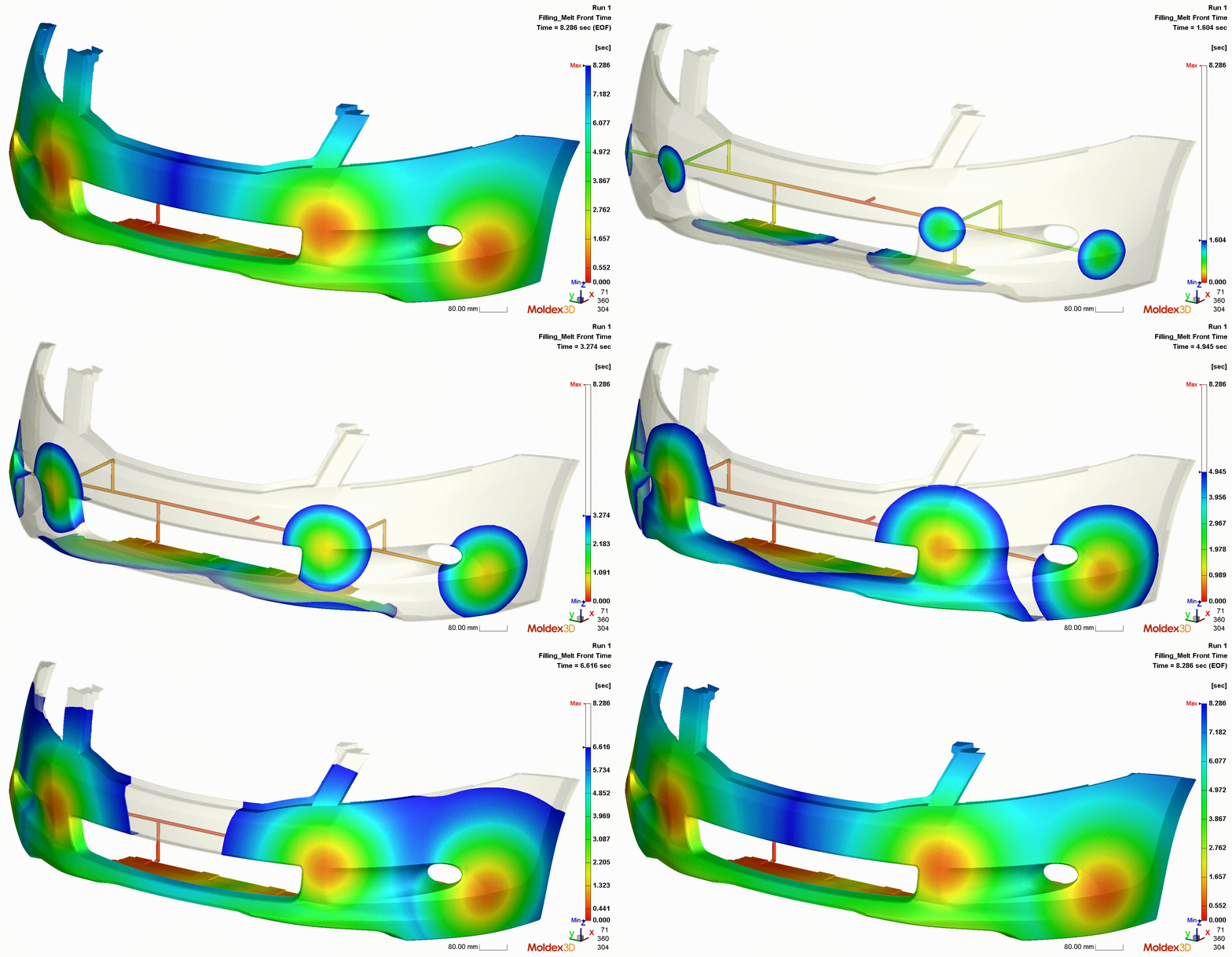
Step 1: Injection molding simulation of the bumper in Moldex3D
To assess the orientation of the fibers in the final product, start by performing an injection molding simulation in Moldex3D. It is a powerful tool and yet easy to use, considered a market leader for plastics molding simulation and fiber orientation prediction in injection molded parts [1].
Step 2: Utilising the injection molding simulation results
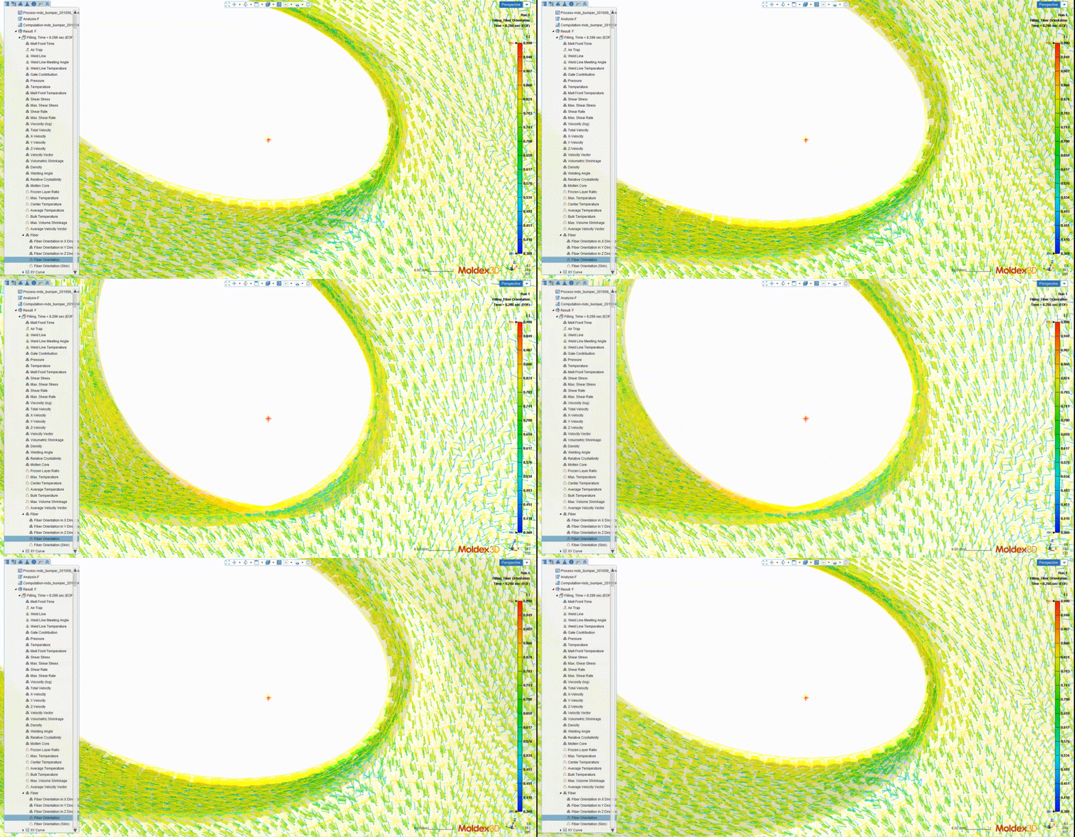
Several alternative ways to make use of the fiber orientations in the subsequent LS-DYNA model exist. Based on our experience, we have two preferred ways of working. One way is to work with Digimat, an add-on material modeling software from e-Xstream. You can couple Digimat to LS-DYNA in simulations, and all the files needed by Digimat can be output directly from Moldex3D.
Another option is to use the mapping software Envyo® from DYNAmore. Fiber orientations, including possible weld lines from the injection molding process, can be mapped to existing shell or solid meshes in your LS-DYNA model. You can also perform homogenization of material properties when applicable. For the following structural analyses, we recommend the LS-DYNA material models that support anisotropic elastic and plastic behavior due to the fiber orientations, e.g., *MAT_OPTIONTROPIC_ELASTIC, *MAT_ANISOTROPIC_ELASTIC_PLASTIC, and *MAT_4A_MICROMEC.

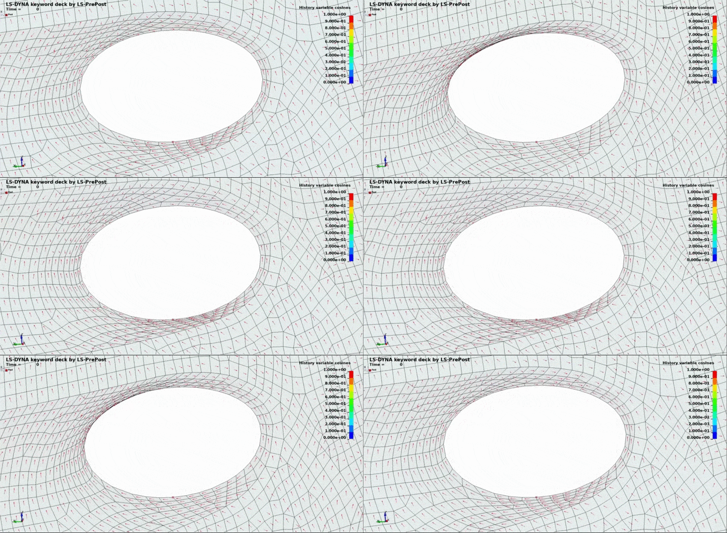
If you are already using another software than Moldex3D for the injection molding simulations, Envyo also has interfaces to other software.
Step 3: Using LS-DYNA to check the bumper performance for the impact load
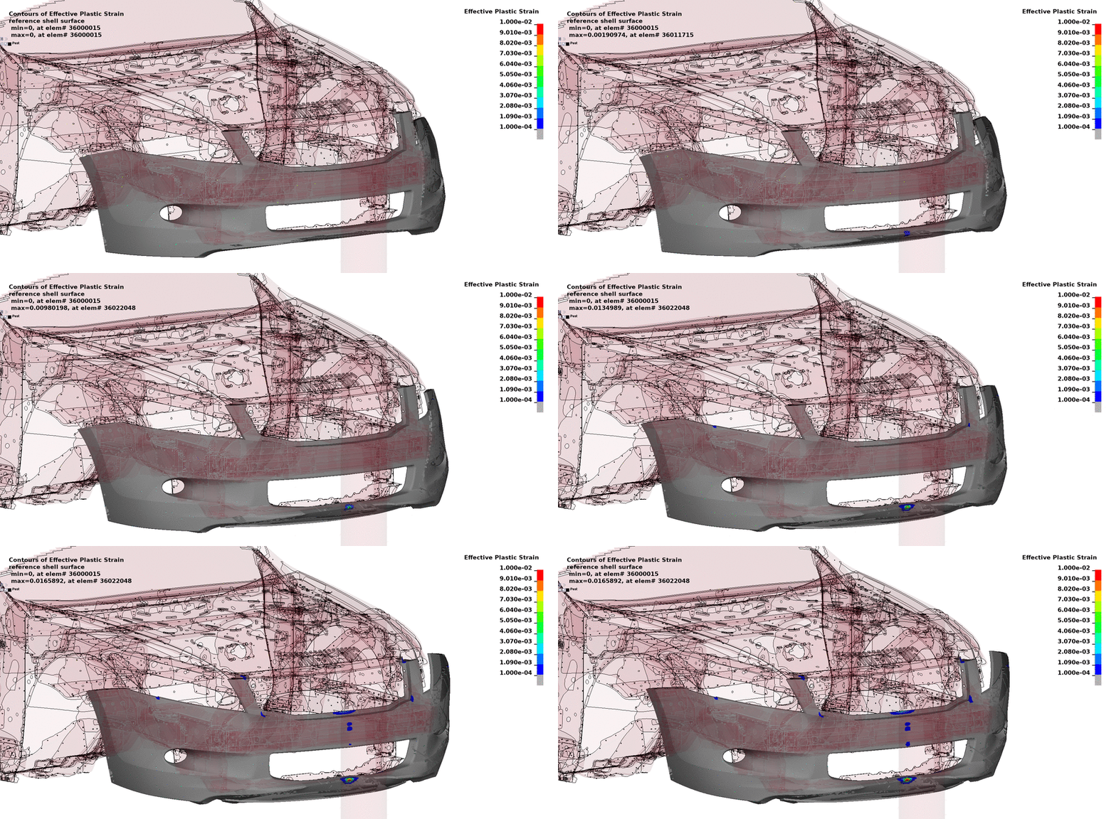
After mapping the fiber orientation from the Moldex3D analysis using Envyo or Digimat, the LS-DYNA vehicle model now includes a bumper containing mapped fiber directions. The pole impact simulation is performed as usual, illustrated in the figure below, and the verification of the bumper's performance can take place.
To learn more
Simulations have time and again proven to be a cost-effective product development tool that avoids costly tooling redesign. We have the software and knowledge required so that you may learn to perform these simulations yourself. We will guide you all the way, including training and support. To learn more, please contact one of our technical experts listed on this page.
[1] Kunc, V., Warren, D., Yocum, A., Wu, F., 2017, “IV.3 Predictive Engineering Tools for Injection-Molded Long Carbon Fiber Thermoplastic Composites – Oak Ridge National Laboratory”, LIGHTWEIGHT MATERIALS FY 2016 ANNUAL REPORT, U.S. Department of Energy, Troy, Michigan, September, 2017, pp. 125-141.
The car used in this demonstration is a modified version of the publicly available Honda Accord model, provided by NHTSA, https://www.nhtsa.gov/crash-simulation-vehicle-models.
