Hotforming of aluminum
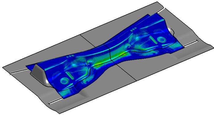
Simulating Forming Processes
When simulating a forming process, the main task is to follow how the part is changing through the various forming steps. One needs to mimic the physical process as accurately as possible in every step. To accommodate this, the user should have the possibility to choose the most appropriate solver and method required for the present forming step. LS-DYNA contains multiple solvers that can either be used individually or combined to create a multiphysics analysis, all within one single license. Below we present a flowchart of the forming process of the aluminum part. The geometry and the material state are transferred between the different process steps through a virtual version of the actual component. Multiple solvers and functionality are used through the simulation process using the same license and software.

The benefits of doing virtual tool and process design before going to hard tooling are several. First of all, possible issues with the forming process can be identified, such as wrinkling and tearing. These issues can be addressed and solved before producing the hard tooling, saving a lot of cost and development time. The press forces can also be determined through simulation, enabling the tool designer to dimension the press line and amount of blankholder force. Furthermore, the out of tolerance deformation due to springback can be evaluated and compensated for in the tooling geometry.
Deepdrawing and Hot Forming
Conventional deep drawing can be a challenging task, but the simulation setup on the other hand is quite straightforward. Setting up the simulation process chain is made easy with the use of tailored software such as DYNAFORM from eta. The die designer quickly gets acquainted with the various tool parts and is guided through the forming process parameters, such as the tool movement and blankholder forces. DYNAFORM also helps with choosing the proper LS-DYNA parameters to use with the various simulation steps. Therefore, there is no need to be a simulation expert to run these types of problems.
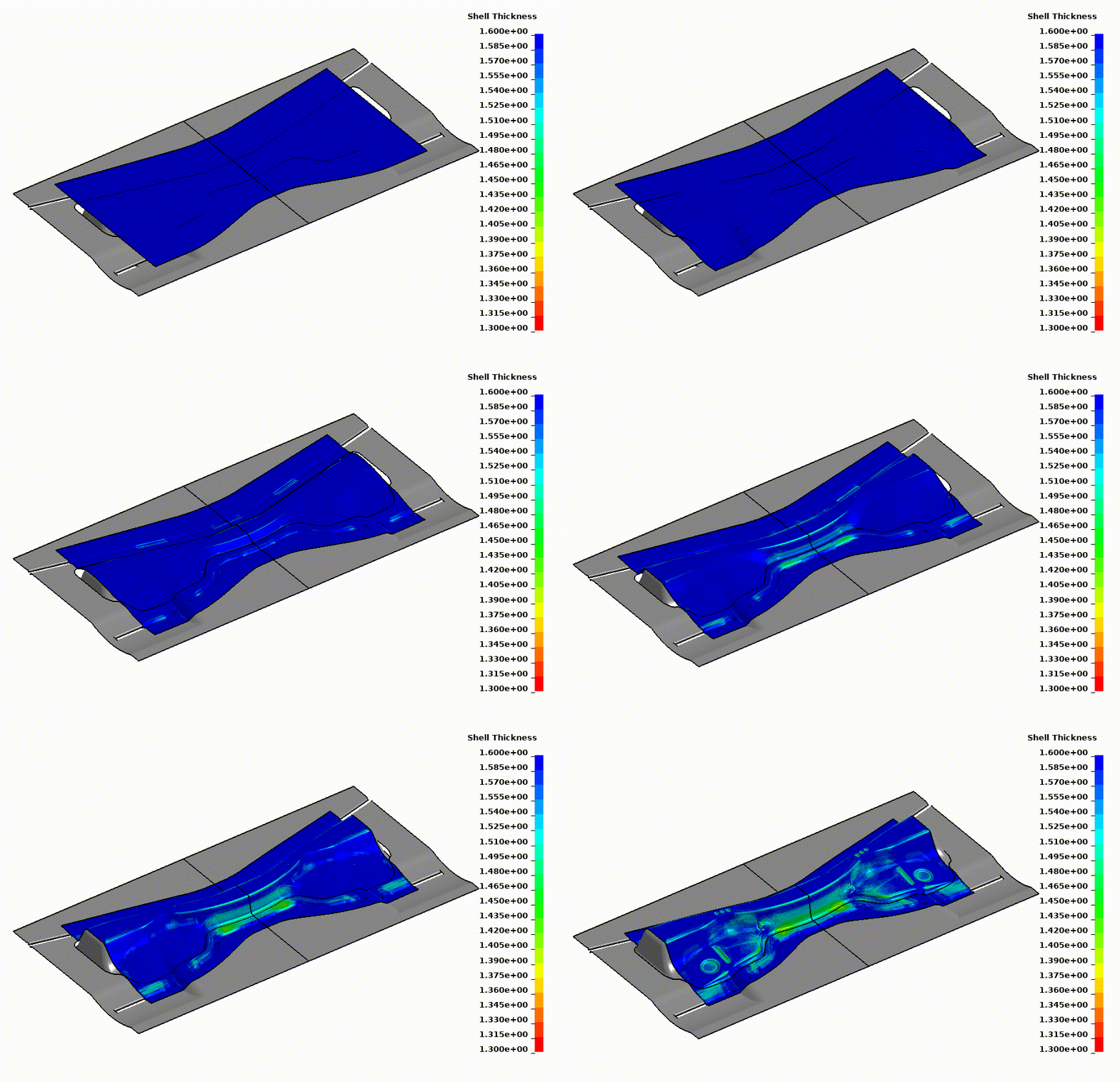
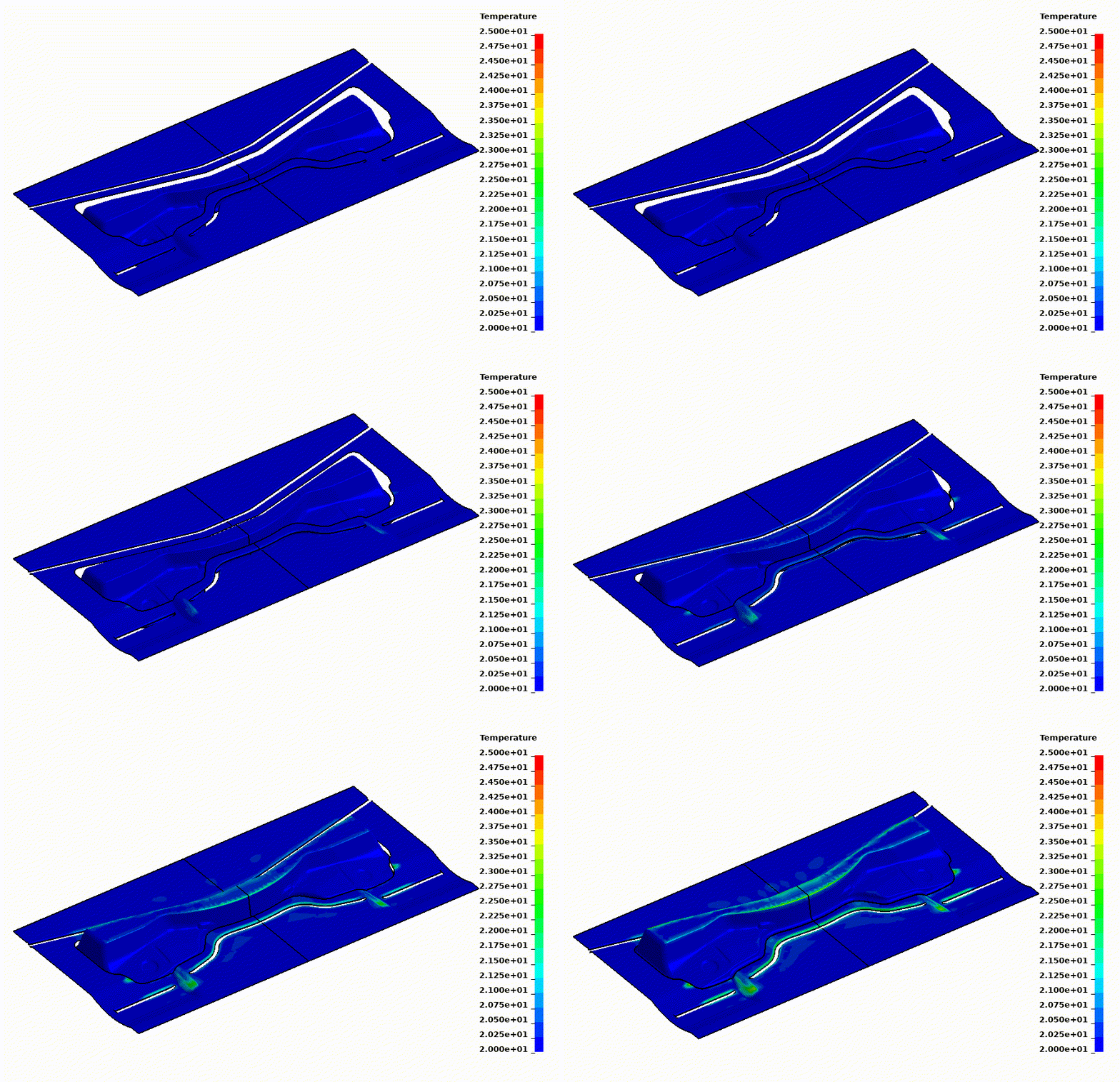
When simulating a hotforming process, thermal physics are added, and the simulation problem becomes multi-physical. The proper way to solve this is to use a coupled approach where the two physical regimes exchange information. Thus, the thermal problem affects the mechanical, e.g., by changing the material properties due to temperature. The mechanical problem affects the thermal, e.g., by cooling through contact between the tool and the blank. As always, the secret is in the details, and having a sound formulation of the problem makes the simulations much more accurate. For instance, one major issue is being able to predict the temperatures during the forming process accurately. This is accommodated in LS-DYNA by allowing the tooling to heat up by the blank and by precisely modeling the heat transfer between the tool and the blank, e.g., as a function of tool pressure.
Describing aluminum at elevated temperatures
It is well known that temperature affects the blank material. First of all, as the material heats up, it expands and subsequently shrinks during cooling. The shrinkage affects the residual shape of the part. Also, as the material heats up, it generally softens. This is why it is essential to model the temperatures accurately, since a hotter part of the blank will inevitably strain more than a cooler part, which could render a part with excessive thinning. Aluminum sheets often have different properties depending on the direction of the blank. It is due to, e.g., texture and/or rolling of the sheet. Tensile testing of aluminum at elevated temperatures shows that these properties also depend on the temperature. Thus, depending on the material temperature, the material is either more prone to material draw-in or thinning. The material models in LS-DYNA can include this behavior and account not only for the thermal softening, but also the difference in anisotropic properties.
Forming simulation, Springback and Springback compensation
In this case, the forming simulation process starts with a tool design suggestion which is imported into DYNAFORM where the simulation process is set up. The blank stretch is generated using drawbeads with a constant gap between the binder and the blankholder. Thus, the first issue is to determine a gap that renders a part without tearing but still has a sufficient amount of stretch. The blank thickness is 1.6 mm, and several different gap sizes are simulated to find a process without tearing.
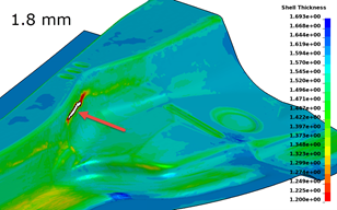
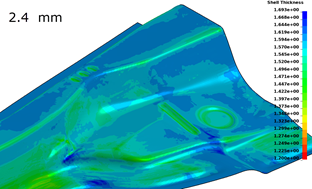
As the blank stretch is reduced to eliminate the risk for tearing, the risk of excessive springback is increased. Springback is a phenomenon where the elastic stresses are released as the component is removed from the die. The residual stresses force the part out of tolerance. In this case, the deviation after trimming, springback and cooling of the part is approximately 5.3 mm, which is not acceptable, see the illustration below.
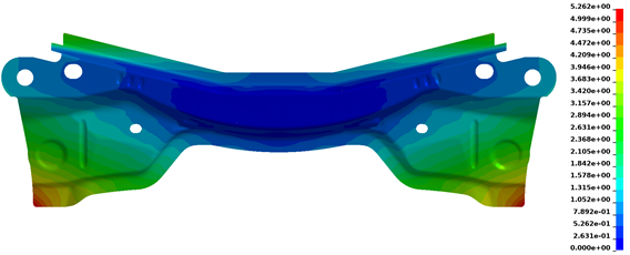
There are several ways to address springback deformation, where one is to compensate for the out of tolerance in the tooling. The part deviation is applied in the opposite direction in the tooling with a scale factor, which causes an overbending of the geometry. The idea is that as the part spring backs, it should attain the nominal shape. In this case, a scale factor of 1 is used, and new tool geometries and trimming curves are generated by LS-DYNA and simulated using the same process settings as before. Using springback compensation proved successful in this case as the out of tolerance deviation was reduced to approximately 0.5 mm.
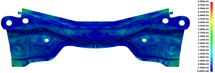
In this example, only 1 iteration of compensation was performed, but the process could be repeated to improve the tolerances further. At this point of the design process, it might be fruitful to check the stability of the process by modifying for example the temperature of the blank, the tool friction, or the material properties, to find out if these variations render parts that are not acceptable.
Simulation time
The computer time spent simulating the forming process is a key factor for a short turn around time of the virtual die design. Here, LS-DYNA utilizes the increasing number of cores in modern-day computers by allowing a distribution of the model on several cores through MPP (massively parallel processing), and the simulation time then decreases with the number of used cores.
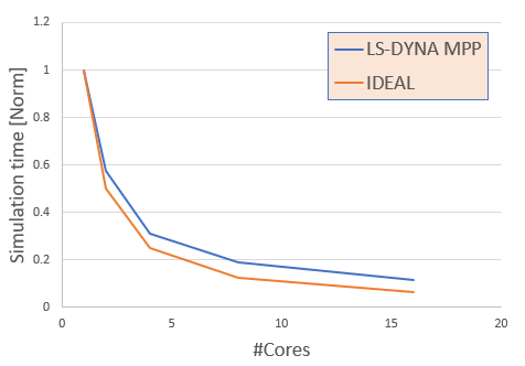
Accordingly, the licensing model of LS-DYNA allows for full versatility when deciding on the number of parallel jobs and cores. Thereby, the customer can balance cost and performance depending on their typical forming processes and parts.
To learn more
Simulations have time and again proven to be a cost-effective product development tool that avoids costly tooling redesign. We have the software and knowledge required so that you may learn to perform these simulations yourself. We will guide you all the way, including training and support. To learn more, please contact one of our technical experts listed on this page.
The part used in this demonstration is a modified version of the 2005 NUMISHEET crossmember benchmark.